Energy Storage #6 - A new BMS

On many social network sites discussing energy storage in general and for boats in particular, there are many views on which BMS is the "best" choice for a boat application. We are seeing an increasing choice of BMS systems available and most fall in to the same category.
Also, in some cases there is a confusion and opinions about what a BMS task should be? That is, battery protection (i.e ensuring that min and max voltages are not exceeded), whether it should deal with balancing or not, present SoC and SoH or if it should be able to manage the current flow in our out? The fact of reality is that to manage a LFP pack on a boat with its special operating conditions you need all of these functions.
For the alternative, "drop-in" replacement of conventional PB (lead-acid batteries) with LFP, these units all have built in BMS that also deals with the dishing out and in of the current. The downside with these are that they do not allow for setting BMS parameters at all. When building a larger system with this kind of battery system you will end up with a plethora of BMS that are unaware of the presence of each other. This may be less than ideal and may not be much of an issue when the batteries are new but rather cause problems as they age. Something we surely will hear more about in due course as most such installations are only a few years old. With few exceptions can you also read out what these embedded BMS are doing and read out the individual parameters to assess if all is as it should be. The only warning you will get is when it fails.
Choosing a BMS means in most cases that the control of the current for load and charging has to be carried out by some relay or contactor.
On a boat, the system has to be "charging opportunistic", meaning that when there is energy to spare from whatever source, then to charge as quickly as possible and then when the battery is full, ensure the loads are using available energy from charging source for as long as is possible before battery power is used.
The key function of the BMS is to always ensure that the battery pack is protected from excess charging and discharging. A plethora of parameters drives the rules that the BMS uses to ensure this happens and that you can trust it doing so safely in the background.
Separate load and charge
A BMS may decide, without prior warning to the user, that it will disconnect from the system. This will happen at two extremes, one will be when the state of charge is close to empty and the other when it is full. Also, a fault condition can trigger a disconnect. If the system is not separated in terms of load and charge buses (paths) what will happen is either a dark ship or perhaps worse, damage to generators and attached load equipment due to a phenomenon known a load dumping. Load dumping can generate short high voltage conditions, above 80 volts and would cause damage to equipment that is powered at this time.
Correct system engineering thus ensures that all the sources for charging are collected on one bus and the loads are on another and that the battery bank and BMS holds these separated. While this allows for separated full or empty disconnect situations, there is still a need for protection to avoid load dumping to occur. Hence some type of hybrid solution is often used where a PB bank is always connected to the charge bus. Such a system may be a first step in a path to full conversion to LFP. This has been my strategy on Artemis until the solar/PV installation becomes a reality.
Different to most other cousins of the lithium battery family, LFP is the one that is closest in nominal voltage range to sort of slip into an existing PB based system. In a nominal 12 volt system the max voltage to charge PB cells varies slightly whether is SLA or AGM type used but should normally not go over 14 volts. 13,8 is typical. This voltage is not high enough to fill an LFP pack to 100% SoC.
The only consequence to this is that if you do not utilise the full capacity of the battery pack is that it lives longer. LFP of this type used on Artemis is shown to live as long as 8000 cycles. As an example, the lithium technology used in most cars is either NCA or NMC and will not even come close this long cycle life. As a side note, never ever allow any of these NCA or NMC chemistries to be used on boat.
My choice for BMS is, as you know if you read the previous posts, for Dutch manufacture of the SmartBMS, 123Electric. This system is based on the distributed module kind where each cell configuration is made "smart" by attaching an active module. The purpose of this module is to report back to the central unit, voltage and temperature and receive command to balance by loading the cell and dumping energy as heat until cells are balanced. It is a flexible system that is easy to install and has means of reading current in and out in separated buses as well as control relays (contactors) for each bus. A smartphone resident app allows for monitoring SoC and battery parameters. Aside from some early system challenges due to physically split battery pack, it has for two years now, worked well. Still, the system has been of the hybrid kind.
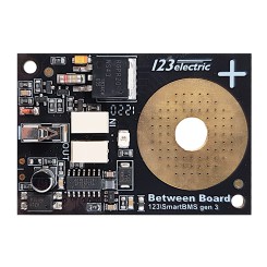 Another issue with the SmartBMS by 123Electric is that is not really well suited for marine environments, the cell based PCB board modules are are fully exposed and not even coated against corrosion. Had the boards not been goldplated copper, they would never have come in question to begin with. But, the soldered components expose the tin to salty air and it would be a matter of time before failure.
In addition, the system became rather complex in terms of cables, shunts, fuses and relays
What the system needed is thus;
- Good envrinmental seal - better than IPX6
- Riddance of mechanical relays
- Built in current monitoring
- Separated load and charge buses
- Monitoring via PC/Display/BT
- Reduced electrical complexity (no modules)
 |
| BMS chassis with Daly BMS and junction box just before it was shoehorned into the slot between the pack and bulkhead. The two blue 35mm2 cables attach to the battery negative. The black connect via fuse and switch to system negative |
Choosing a larger than you need BMS of this kind has the benefit of also reducing the inevitable small resistance any device in the current path will present. A larger BMS has more of these power MOS-FET´s in parallell thus reducing the series resistance and hence the heat generated at very high load currents. All mechanical connections introduce very small levels or resistance, seemingly neglible low but if you crank the numbers at the expected currents you will find that the voltagedrop is noticable. They also add up as resistors in series do. For reference, a cable clamped to an 8 or 10mm post, or your high amp contactor, has greater resistance that what the BMS has.
The installation included a ANL fuse is series with a manual breaker for disconnect.
 |
| This is how simple the system became with the Daly BMS (ANL fuse and BT dongle not shown) The yellow lines are the voltage sense and balance current wires. |
My wiring principle is to never use greater wire gauge than 35mm2 (AWG 2) and rather double up on them as required. It makes wrestling with thick cables more manageable and it makes life a little more comfortable as you need only to stock one type of lug. As Artemis battery is 24 Volts and 2x35mm2 is used this translates to the equivalent of 140mm2 in 12 Volt terms. When I have more hands to help, a measurement of voltage drop will be made with high loads applied.
Work was done over a few hours by first removing the 123BMS. I had prewired the cables with 8mm lugs so that the Daly BMS could read and balance each cell (orange cable). These two cables from each pack was routed to a junctionbox mounted on the same chassis as the Daly BMS. Cable glands on this junctionbox ensures that the connections to the included break-out cable from Daly will not suffer from corrosion anytime soon. Routing the power cables to the fuse and disconnect switch was a bit of a challenge due to the tight space but it ended up being satisfactory. After attaching the BT dongle and putting the temperature sensor inbetween cells the system was almost ready to be activated. The last and very important electrical check was to ensure that the voltages, or order of cells, was correct on the plug on the break-out cable before plugging it into the Daly BMS. I did this twice.
As soon as this plug is inserted in the Daly BMS it is also given power. A small button on the BT dongle allows for wake-up of the BMS. Doing so resulted in my phone app connecting to the BMS. After this was done I also closed the main switch attaching the negative side of the battery pack to the negative load junction. No blown fuses, the system was online.
Another view to show how tight it was between battery pack and bulkhead. The ANL fuse can be seen way below the manual switch.

The only concern at that time was what the app setting actually do. A few of the basic parameters are clear but others not and I have not found any in-depth explanations. All seems to work, charge and discharge was clearly operative as was balancing even though it is unclear at what point and how balancing is actually carried out. In any case I set the known parameters conservatively to be on the safe side.
The app had at times problem reconnecting with the BMS BT, but as I had similar issues with the 123BMS and learned then that restarting my phone worked, this also did the trick for the Daly.
The BMS has a setting for time before sleep. It was set to one hour and I kept it there. What sleep actually means is still not fully understood and what makes it wake up? Hopefully sleep means it will reduce its power consumption to very low levels if there is no charge or discharge current. As this is how I left it when returning back to Sweden.
 |
| The second pack located in the aft/upper bilge area where the original PB cells where located. The orange cable snaking on top of cell is for voltage monitoring and balancing. |
 |
| Next to the BMS is a manual disconnect switch. To the right you can see the BT dongle |
 |
| Birds eye view of the first batterypack located beneath the saloon seating |


Comments
Post a Comment